Geometry-based MatCap light probes, and re-lighting in compositing.
Light Probes and a Little VFX History
We will get into the subject at hand soon enough. First let’s set the context:
Photographs of chrome spheres are used in visual effects production to record actual location lighting and reflection. These are called “Light Probes” (see Paul Debevec’s research that made them standard on-set). Once a picture of a light probe is unwrapped to a flat texture, it is the primary driver of image-based lighting (IBL) on CGI objects. IBL is one of the core methods in use to re-create the conditions at the time of photography for CGI objects added at a later date. Most 3D software use the images directly as lighting by mapping them to spherical area lights, or actually project the image back onto surrounding stand-in geometry, but it is not unusual to extract and map brighter highlights to individual lights for greater control.
Before High Dynamic Range IBL was standard, lighting was often an educated guess, and when artists had chrome reference, they would either match the photograph by eye, or texture map a sphere with the image — using it to place lights by tracing a vector from the center of the sphere outwards through the middle of a texture mapped highlight. This would identify general light placement, but since most of the images were standard dynamic range, it was necessary to isolate color from the gradient exposure around the highlight (as the exposure reduces, the hue of the light is apparent, and is revealed in the gradient), and guess at the intensity. Although it is a more archaic procedure, good results are possible in this manner, as is apparent by this early use of the technique at Digital Domain from this 2000 article in Computer Graphics World:
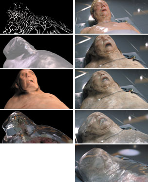
Lighting this scene required yet another trick, incorporating an innovative use of newly published research by scientist Paul Debevec, known for image-based lighting techniques that enable CGI to be lit with the actual lighting from a live-action set. The Digital Domain team already had a “light pass” of the scene that made use of a light probe, a perfectly mirrored chrome sphere that captured the position, color, and brightness of all the lights in the scene. Debevec’s research is based on creating lighting exposures from the most underexposed to the most overexposed. But Cunningham had only one pass at the one exposure, so he simulated the other exposures to derive and match the color temperature of the lights.
Although HDRI images are preferred, they are not required, as was demonstrated in 2001 by Industrial Light and Magic for the film Pearl Harbor. Below are examples of lighting tools in production by ILM for Pearl Harbor (2001), using standard range sRGB chrome sphere imagery, while removing inherent highlights (which are clipped) – choosing to use CGI lights in the same position to infer High-Dynamic range sources. These images were captured by the VFX supervisor on-set with a chrome viewing sphere using a film camera, and used to render with then novel lighting techniques that are now standard.
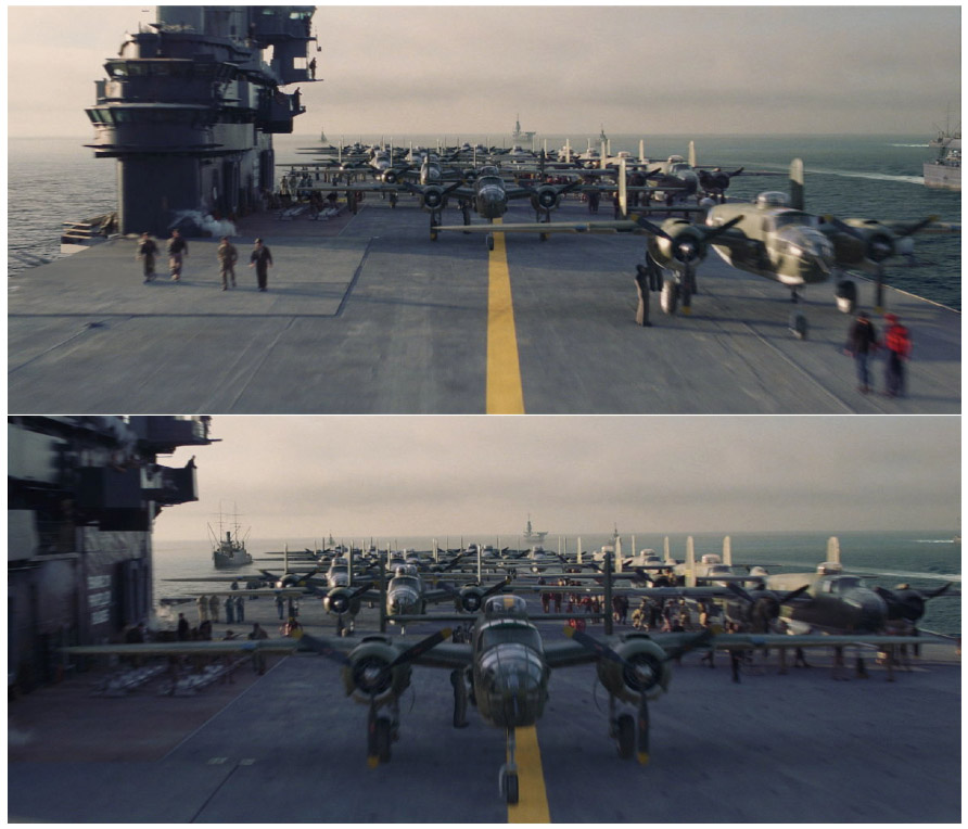
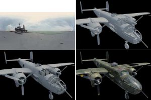
Before the direct use of the Light Probe as lighting information, the chrome sphere was just data to assist the artist, and the work was still done by brute force. Full range light samples were not, and are not an absolute necessity, as even a standard dynamic range spherical reference has value to the artist. Such lighting information is now expected to be acquired during filming, but it is more often the case that no lighting information was gathered on-set, and that artists are still left eye-matching the scene to rebuild specific lighting.
SIGGRAPH research over the past few years has focused on recovering lighting information from a scene by analyzing highlights, or directly remapping environment lighting from a person’s eyeballs, or other spherical objects in the frame — it is almost always always a challenge to identify objects that easily provide spherical projections. This type of recovery is an invention out of necessity that is far from ideal, but can produce viable results, but it is often highly technical, and difficult for the standard pipeline to recreate.
As this article will demonstrate, it is also possible to extract lighting information from an arbitrary surface using simple tools. This article proposes a novel lighting extraction method that uses forms within the scene, that at its simplest identifies the general direction of light sources in an image. Also discussed is the inverse of the technique, which generates interactive lighting, or additional re-lighting on photographed images entirely in compositing, using derived normal maps and uv re-mapping.
Mapping types
It is necessary to establish some common nomenclature, and understand what type of 3D texture mapping and render passes are being used.
1. The uvMap
Coloring a computer generated surface is accomplished generally with procedurally generated textures, parametric projected texture maps, or uv projected texture maps. UvMaps are essentially a customizable lookup coordinate system for a two-dimensional image, along the image xy coordinates, but are specifically called “uv”, or “st” maps in 3D graphics. Essentially a uvMap is similar to making clothing, in that a flat object is cut-up to fit around a more complex object, and laid-out as a pattern. The color value of that map directly correspond to the xy coordinates of the texture image. Gradient values are applied in the red channel for the u-direction, and in the green channel for the v-direction, creating a colorful texture map.
Since the uvMap tells the computer where the texture color should be, as the object transforms across the glowing screen, a fully illuminated uvMap rendered with the same transformation by itself can inform us where a resulting color originally came from in texture space. A rendered uvMap can inversely look up image values, and project them back to a flat texture map. This is called Inverse-Mapping.
2. The Normal Map
Lighting a computer generated surface requires that each geometric face have a surface normal. A surface normal is a directional vector that is perpendicular to the face, and is “normalized” to 1 unit in length. When calculated against any given light, the lighting algorithm informs the computer which direction the surface is facing when a light ray is coming in. It is either looking at the light, or is to some degree looking away.
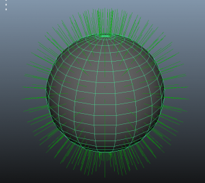 A value of 1 in this calculation tells the computer that it is looking directly at the light, and a value of -1 tells it it is looking away from it, and those variations attenuate the intensity of the light. Lighting calculations aside, the map merely tells each surface where it is looking in the world. This can be represented in texture form by scaling the values to fit a range of 0-1, and putting the xyz coordinates in an rgb image known as the normal map. This map directly represents the surface direction, but not its 3D coordinate.
A normal map typically looks similar to this. There are many types that vary based on need.
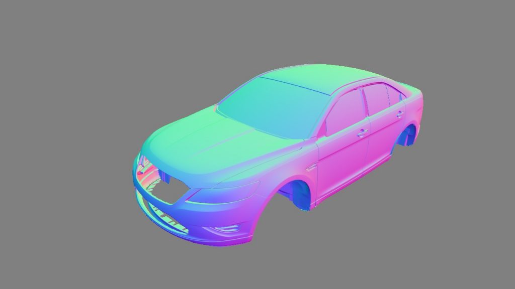
Some normal maps are directly associated with the geometry and the vector direction and variation in world space. The mapping can also be associated with texture tangent space, or camera space. A Camera Space normal is a vector in xyz that tells whether a surface is looking directly at the camera or not, so it changes as the surface rotates in the viewport. It is not stable on the surface during render time, but is always in relation to the camera, and produces lighting that is always camera-centric. Camera-space normals are the one that interests us most for this technique, as we want to use the normals to identify the color of the material lighting environment as much as possible.
Inverse Lighting
There are systems that use photographs of chrome spheres or objects to directly find the three dimensional light vector by associating it with a 3D model for analysis. The surface is used to ray-inverse the reflection vector (r=d−2(d⋅n)n if you are interested in formulae) to identify a light source (most recently ILM’s LightCraft). The first such tool may have been produced at Centropolis Effects for the movie Eight Legged Freaks. Plans on this author’s side to project back on to a spherical environment from an arbitrary surface using simple reflection vectors in 2002 never got past the planning stage, so an actual production tool that recreates chrome sphere information is quite impressive.
The level of coding necessary to build tools that only use a single image to sample the light sphere, and not go through the entire mapping process are typically proprietary to VFX facilities, and not available to the general public. However, there is a simpler way to get useable results with off-the-shelf tools.
An Off-The-Shelf Technique
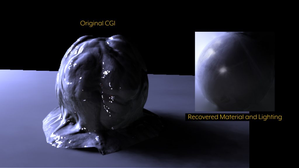
In 2009, the method proposed in this article was constructed as a simpler way to identify the general lighting direction, or capture materials from complex objects into a MatCap format — a method to generalize appearance and lighting into a single image. The method uses uv-inverse mapping with camera based normals instead of a standard uvMap, all in a compositing package.
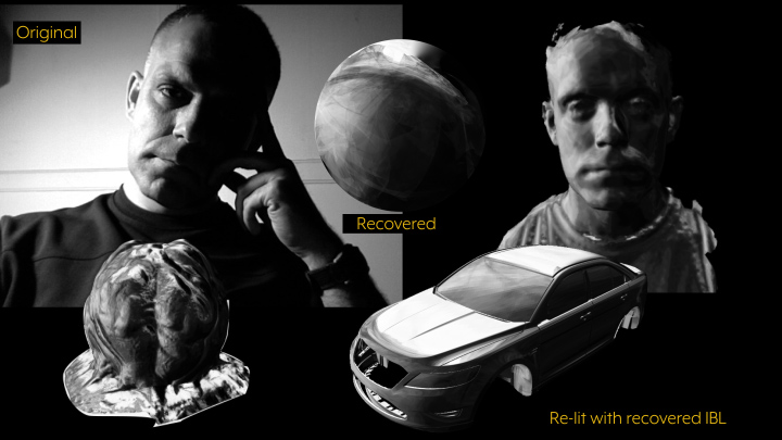
During production of the television series FRINGE, in 2009, while using a commercially available uvMapping tool in Adobe After Effects (which allows inverse-mapping), the uvMap associated with the rendered image was swapped with a camera-based normal render. The resulting image looked like a sphere, that was lit in the same manner as the image in the scene. It was quite a surprise to see it. Quick verification with the show’s Technical Director proved that the image reasonably recreated a virtual “dirty chrome sphere,” in which highlight and lighting direction were identified, as was general surface color. This image was fed back into the original camera normal map, using the same uvMapping tool, and it reasonably recreated the original image. Further testing the recovered lightMap on novel geometry as a MatCap (explained below) produced similar results.
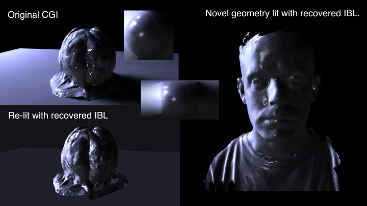
Encouraged by the previous test, a rough 3D model of a face was rendered and two-dimensionally warped to fit matching features. This is not perfectly accurate, but is a close enough approximation to recreate a general “light probe”, or material capture. It easily identifies point and soft light sources, although once more tainted by color of the surface. You will note that the 3D surface is incomplete, and rough in areas, which explains some of the eccentricities in the recovered IBL. Other oddities in the reconstructed image are due to the method in which the commercial plug-in recreates the inverse color mesh — which took some adjustments to refine to this point.
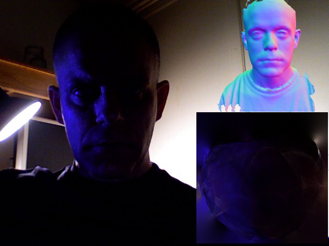
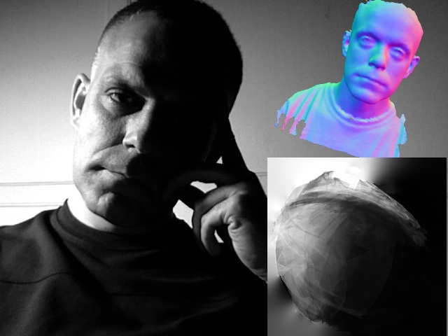
Still, not too bad.
Re-lighting Results
The images looked like a reasonable reconstruction of the original lighting in the photography, but the faux light probe also contained surface color. Using them directly for 3D lighting would not produce accurate results, but if the images were unwrapped to 2D textures, and wrapped around a sphere, they could be used to place lights that match the original photography. There is also some clue as to the original color of the lights, but the reconstruction would be manual, as had been done in the early days of lightProbe-based lighting mentioned earlier. If the original image was photographed in High Dynamic Range, the reconstructed faux lightProbe should still have much of that information.
As this is intended to be an entirely composite driven process, we will leave the 3D reconstruction of lighting for another discussion, and focus on implementing the lighting as a standard Material Capture in the compositing engine (in this case Adobe After Effects). The images are basically MatCap probes from novel geometry, so it follows that they can be used directly in that manner to create a seemingly lit surface.
What is MatCap?
The matCap method was popularized around 2007 in Zbrush software, but seems to have earlier origins. The ShadeShape plugin from ReVisionFX (circa 2005) seems to be using a similar algorithm, and predates the Zbrush implementation by several years. Zbrush has a tool to rebuild the MatCap by defining which normal gets color from an image, but it is a highly subjective process.
If you want to know the basic code behind the process, here it is: uv = normal.xy. UV coordinates are swapped with XY normal coordinates to produce a simplified lit result. If you want to know more about it, the Foundry website has a great breakdown of MatCap shading. (updated information about the origin of this process will be posted as it is located)
Results
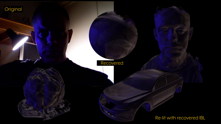
Here are some results using roughly placed normal maps to recover IBL MatCap-style faux light probes, and retargeting them using other rendered normal passes as uvMaps from different objects.
A. This is an example of the very first result from exact rendered normals on a CGI object.
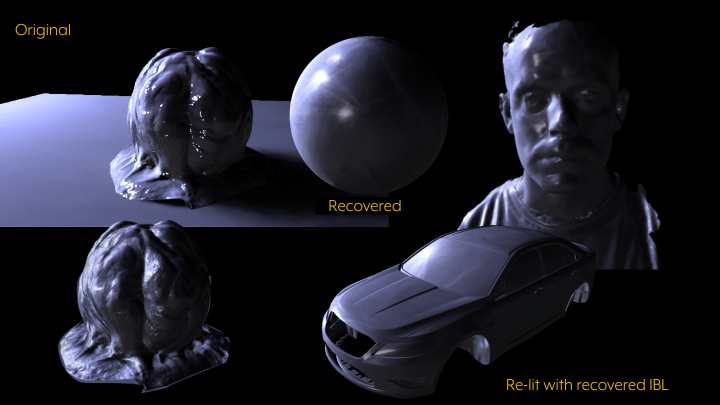
B. Here are two results from the simple hand-placement of incomplete normal maps from photography.

Motion Testing Recovered Lighting
The next step was to apply the method to moving imagery, in which an image sequence could also be used to create dynamic MatCaps from an arbitrary surface. Further testing with a roughly positioned match model of a similar vehicle, created similar lighting results, and the flat texture map could be further processed to approximate the core light sources in motion, that were once reflected in the surface.
This is a rough reconstruction from screen-spaced normals. artifacts are the result of settings in the plug-in, that were adjusted to retain highlights, versus a smooth surface.
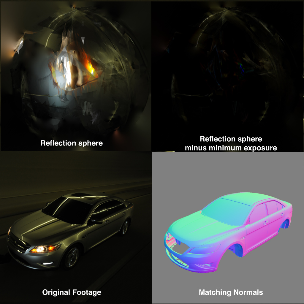
The video below shows the recovery in-motion.
Standard image processing techniques, such as subtracting the minimum average exposure, color keying, and rotoscope are typical methods for cleaning up these images, but are not a complete solution to cleanly identify lighting. These images are “dirty,” and once mapped may only suffice as a lighting guideline for the artist.
Extended use of MatCap in Compositing
Interactive lighting
Why not use a dynamic MatCap itself as a lighting tool? It contains a lot of the necessary information to recreate the lighting. Furthermore, if a chrome sphere sampled in camera can be used for lighting, why not a virtual chrome sphere? The matcap method is not limited to 3D objects alone, but composite-based objects can also be approximately lit with 3D rendered chrome spheres using these techniques.
In the following real-world case a man is supposed to be falling down an elevator shaft. Actually he is laying on a greenscreen while the camera moved, and it was the job of the VFX team to create the illusion he was falling down this shaft. To sell the illusion visually, the lighting in the environment should interact with him. Typically this is done by match-moving the actor’s performance in a 3D animation package, and re-lighting that — which takes a lot of time.
Instead, the actor was extracted from the greenscreen, his position stabilized, and then “dropped” down a CGI elevator shaft in a 3D composite. The alpha channel of the footage was used to build inflated normals (a technique dating to 1991), and those normals given a further bump map from the original footage. Although not perfect, it was reasonably close, and the action so brief that the exact reconstruction was unnecessary.
In the 3D scene, a virtual chrome sphere stood-in for the actor, and that was ray-traced to reflect the environment and all of its bright lights. This image was next stabilized into a square texture map, and used as secondary lighting with the MatCap method. Once the color was modified by the new lighting, the stabilized image was “dropped” in a 3D composite, and mixed with the CGI background, and the illusion complete. The use of MatCap dynamic lighting in compositing worked exactly as hoped, and delivered the final result in short order, and at a cheaper cost.
Conclusion
By using camera normal maps as uvMaps, it is possible to add dynamic lighting in compositing using the matCap process. Furthermore, this process can be used with arbitrary geometry, to inversely build a MatCap from live footage. Using methods that pre-date full dynamic range Image Based Lighting pipelines, it is possible to reconstruct reasonable 3D lighting to match the footage from these reconstructed “light probes.”
It is always best to get full lighting reference from set, and having a full 3D scene is likely to create the most realistic results for interactive lighting on an object. Since the reality of production does not always allow for that, these techniques are cheap, and easily employed to solve the challenge. They will hopefully become part of our standard toolkit, and evolved to a more effective tool.
AG

Updated text for clarity.
Hi and thank you for this great article. I am working on a project at the moment where we are using matcap in 3d to create an extra pass we couldn’t get otherwise. I was wondering if we could do that in After Effects rather than in 3d and this article seems to say we can, which would be great! Do you know any tool/plugin for AE that would allow us to do so? Thank you!
The re:Map plugins from reVision Effects enable this for After Effects. It was used for the original research.
Awesome, I’ll have a look at it tonight, thanks so much!